


Entrepreneurs
Youtubers
Podcasters
Influenceurs
Entrepreneurs
Youtubers
Podcasters
Influenceurs
Entrepreneurs
Youtubers
Podcasters
Influenceurs
Informations
sur notre studio de podcast
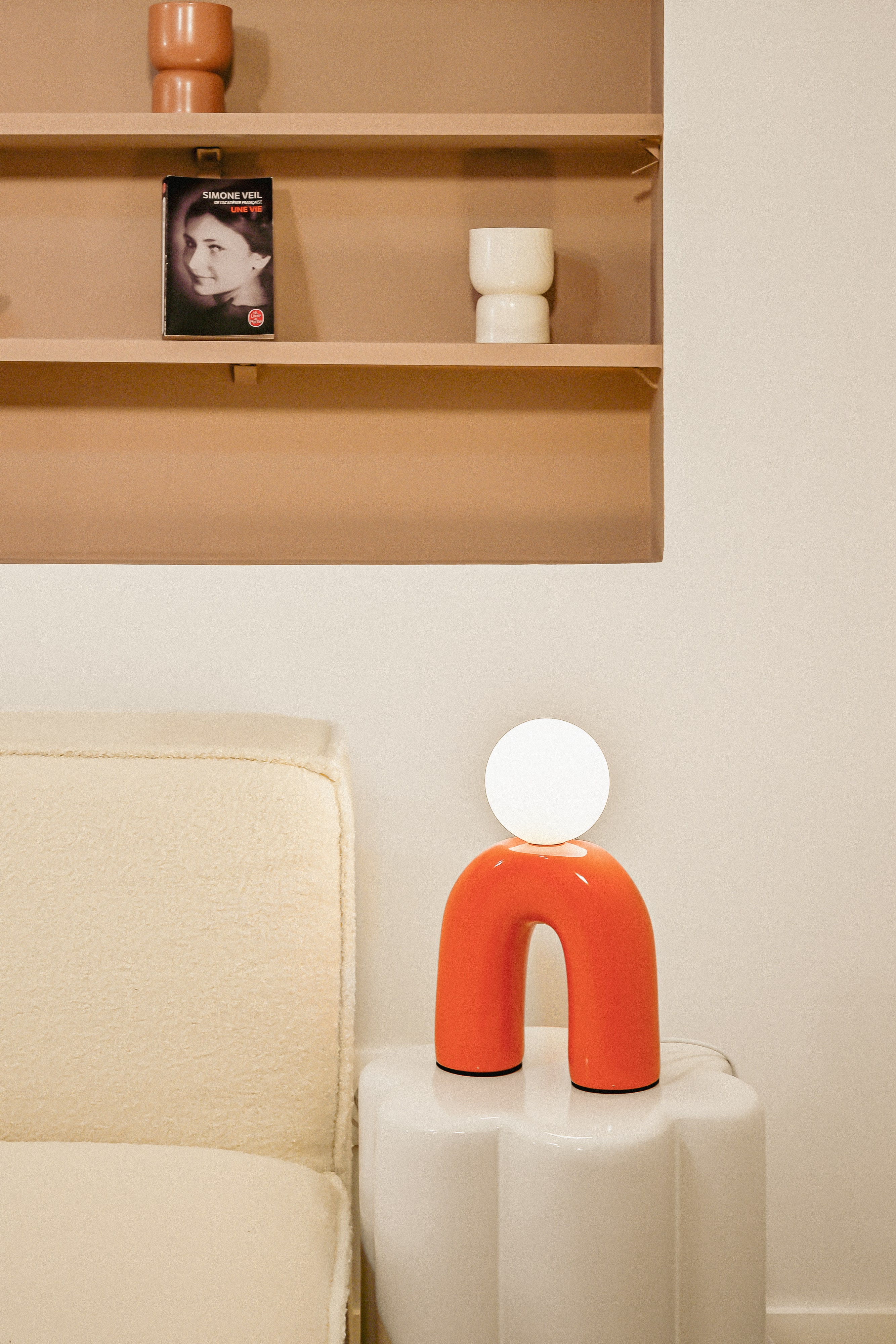
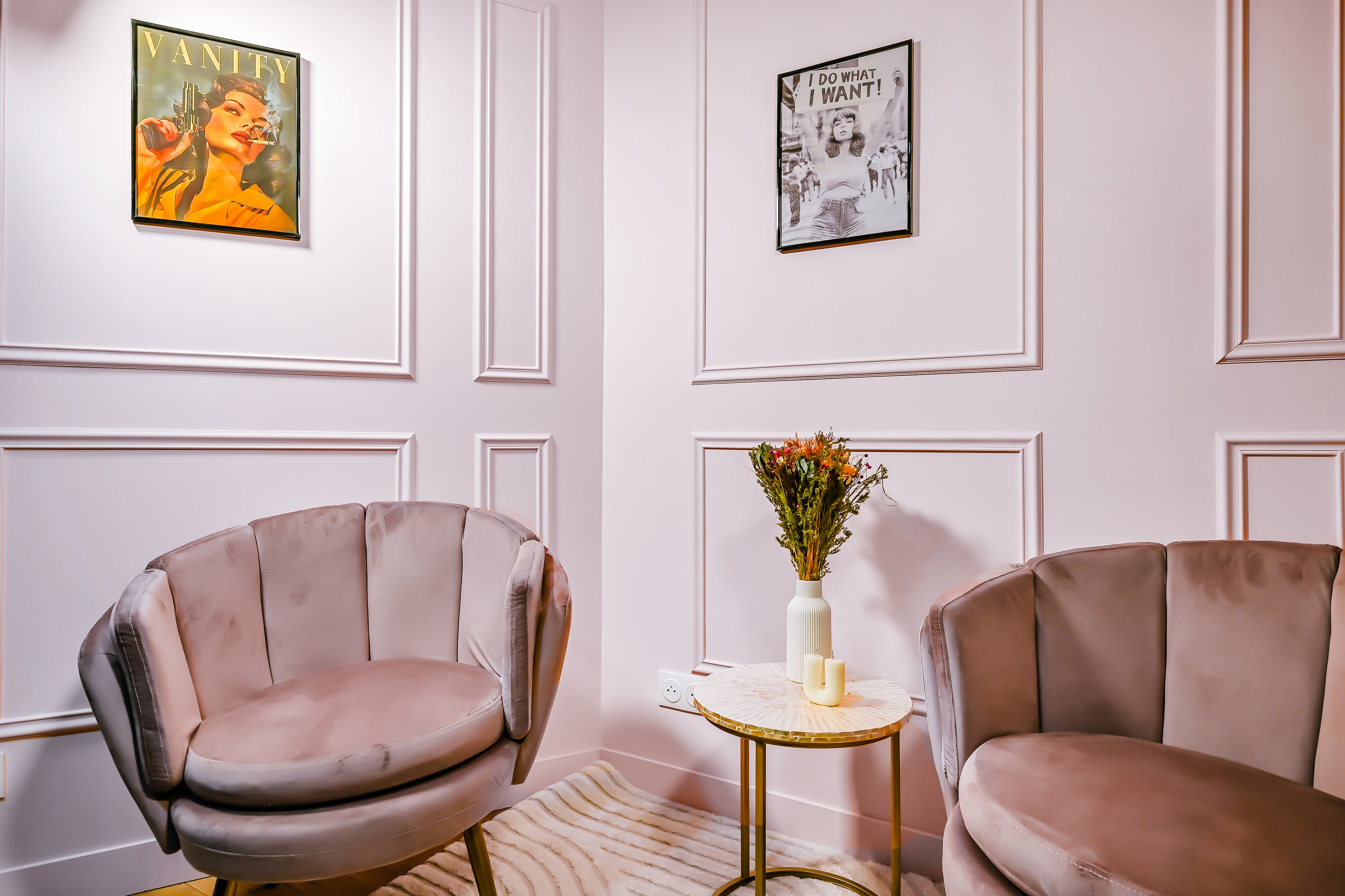
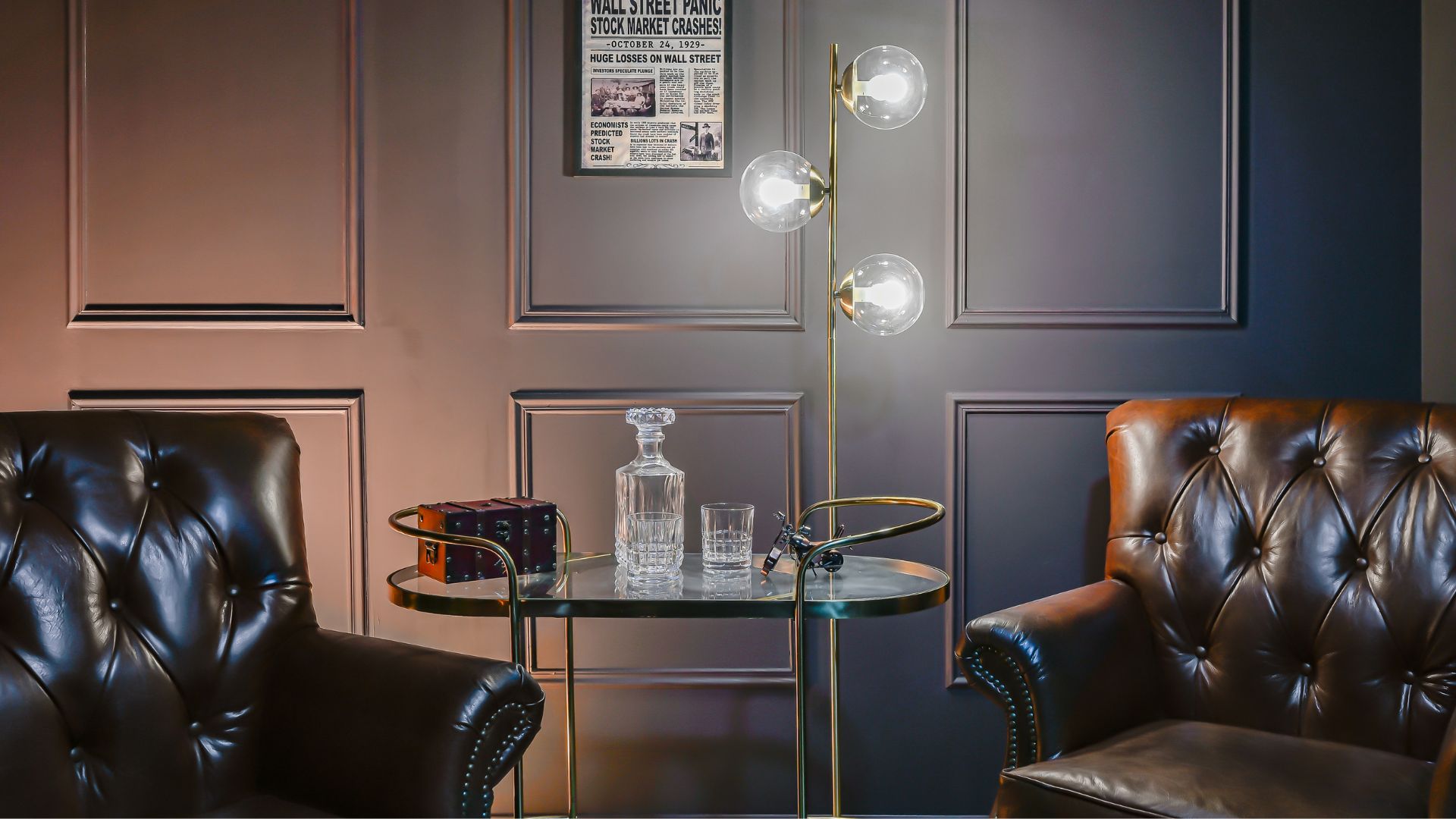
6 décors personnalisables.
Opérateur dédié à votre tournage.
Ouvert 7 jours sur 7.
De 9h à 21h.
14 rue Dulac - 75015 Paris
(2min de la gare Montparnasse)
Visite possible.
Contactez-nousOpérateur dédié à votre tournage.
Ouvert 7 jours sur 7.
De 9h à 21h.
14 rue Dulac - 75015 Paris
(2min de la gare Montparnasse)
Visite possible.
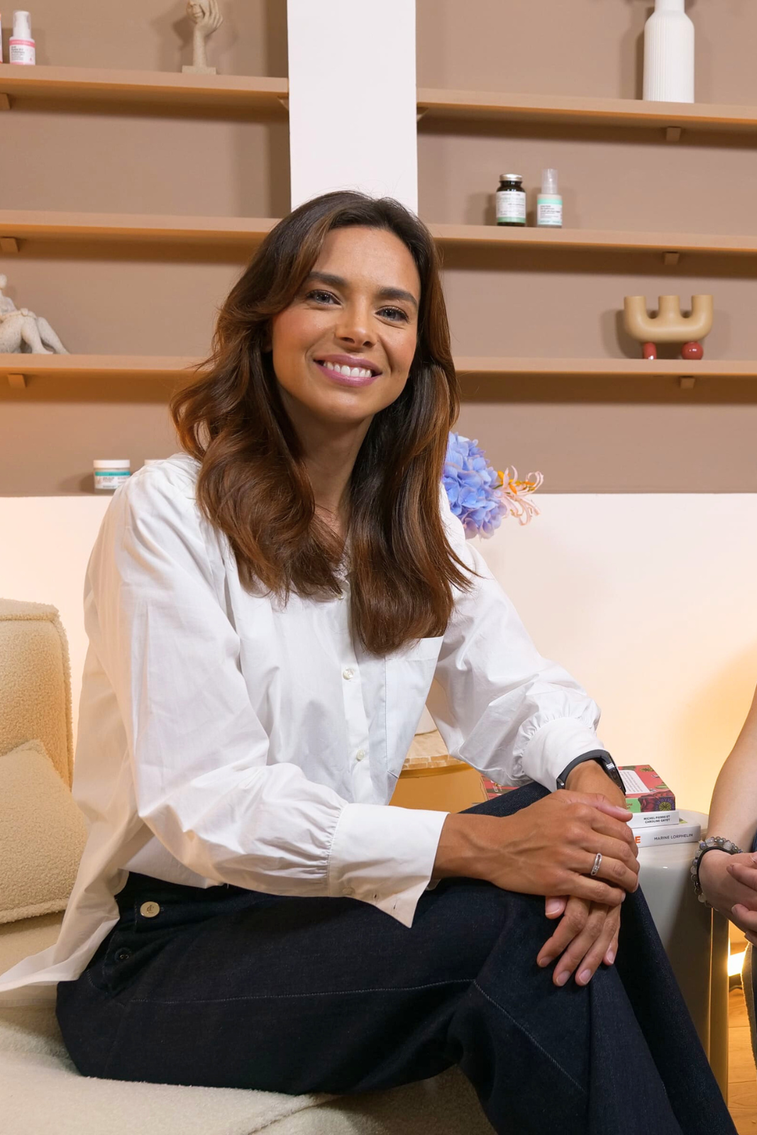
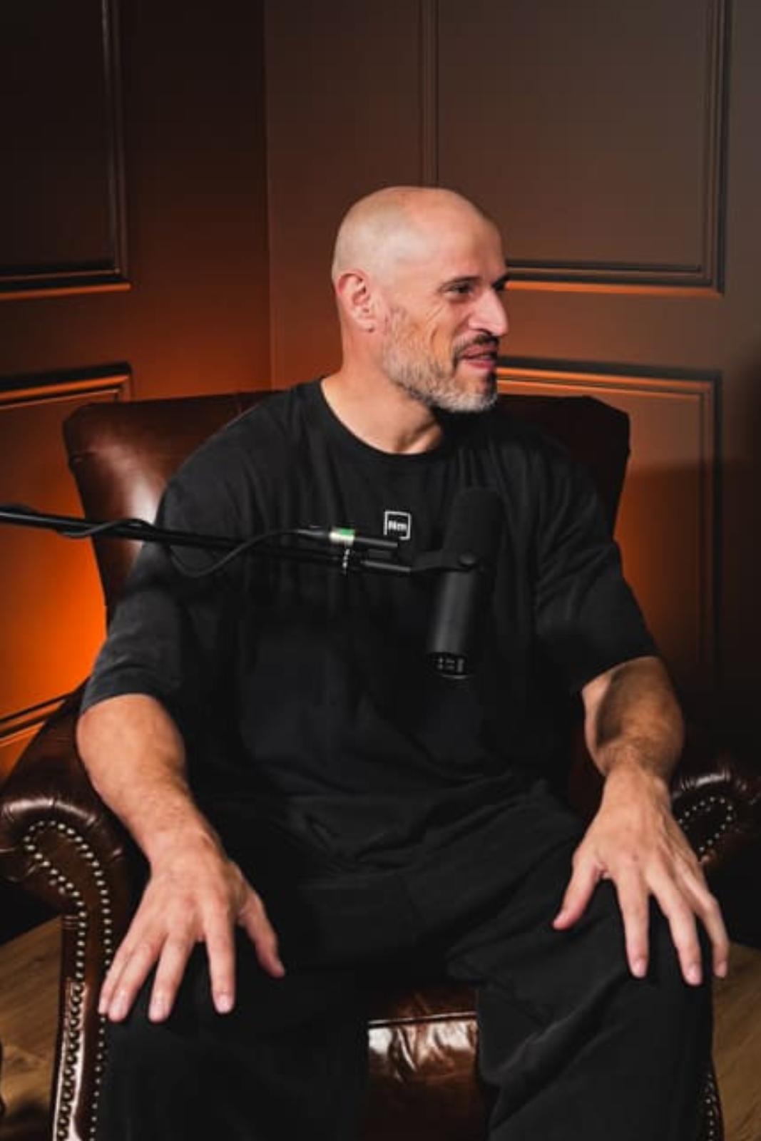
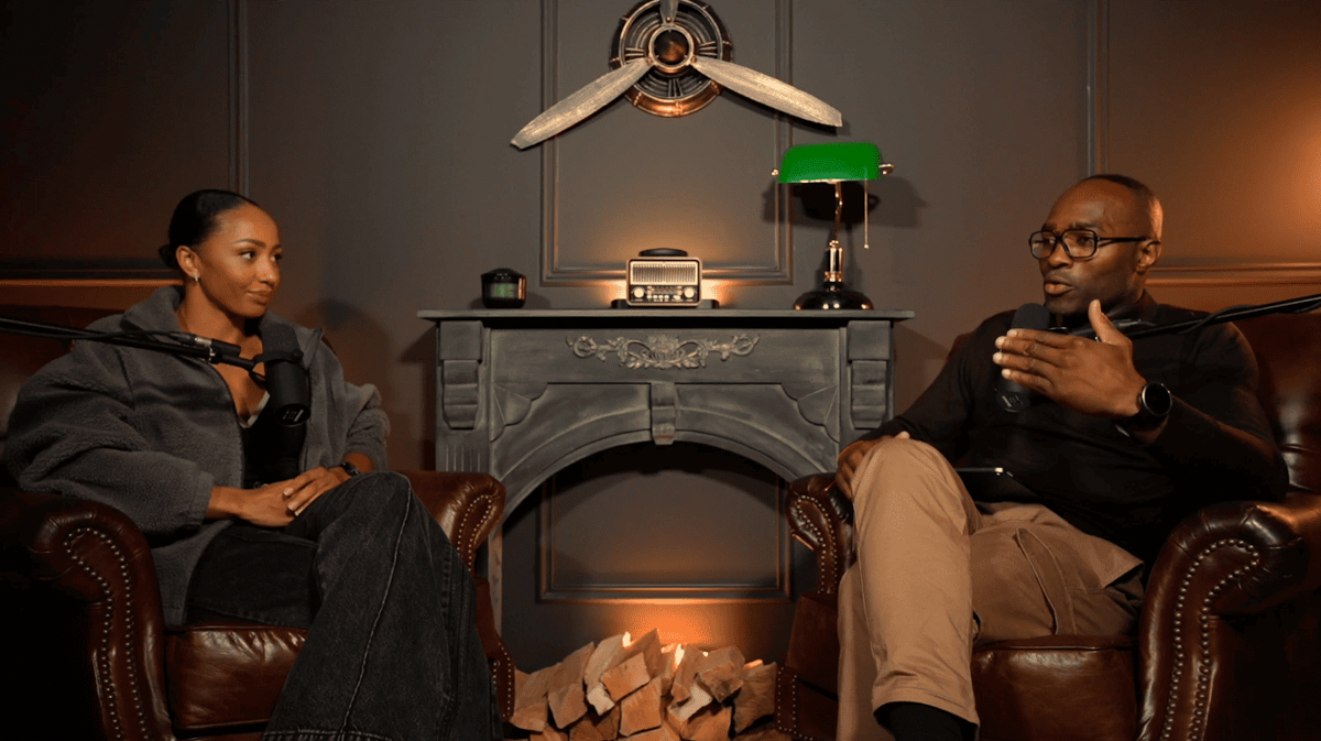
Ici se créent les plus belles communautés
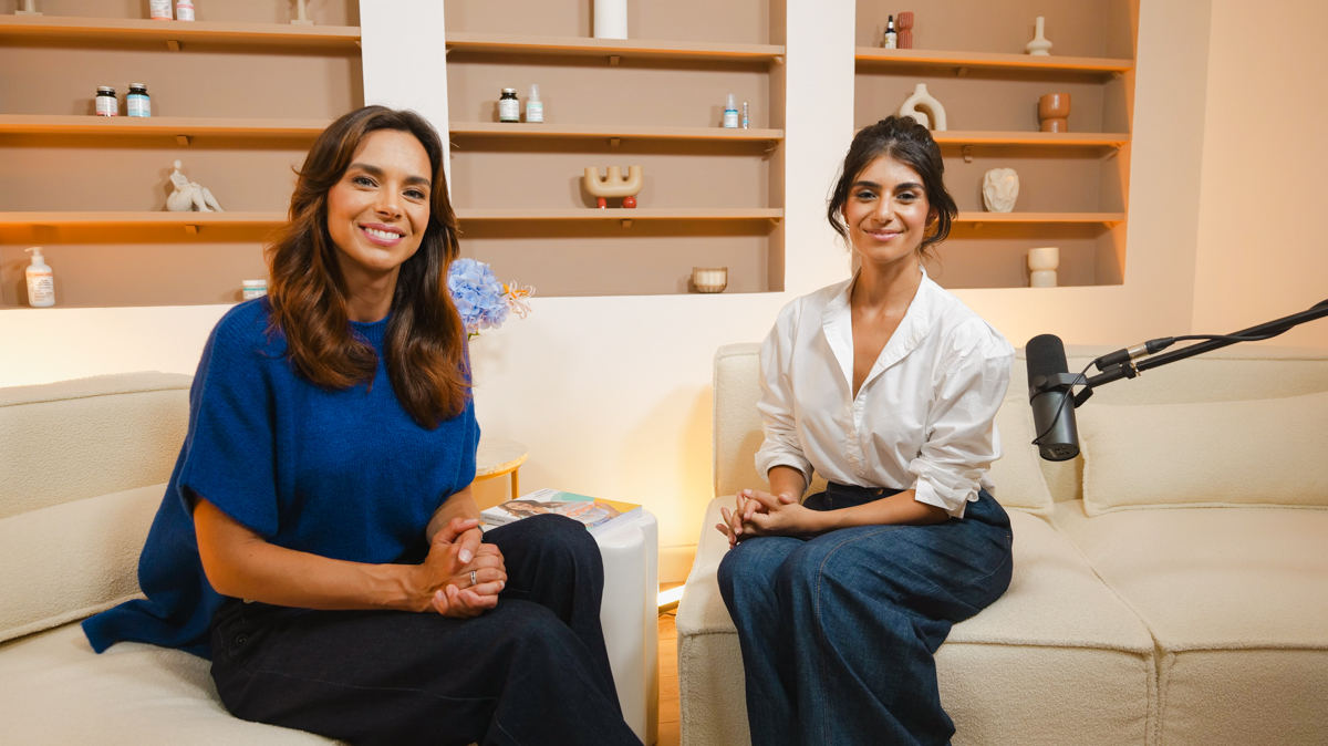
Créez du contenu de qualité professionnelle dans de magnifiques studios spacieux conçus pour la production de contenu en solo, les interviews avec des invités, et bien plus encore.
Enregistrez en toute confiance dans des studios insonorisés qui allient confort, son parfait et esthétique professionnelle.
Enregistrez en toute confiance dans des studios insonorisés qui allient confort, son parfait et esthétique professionnelle.


Les meilleurs créateurs utilisent nos studios
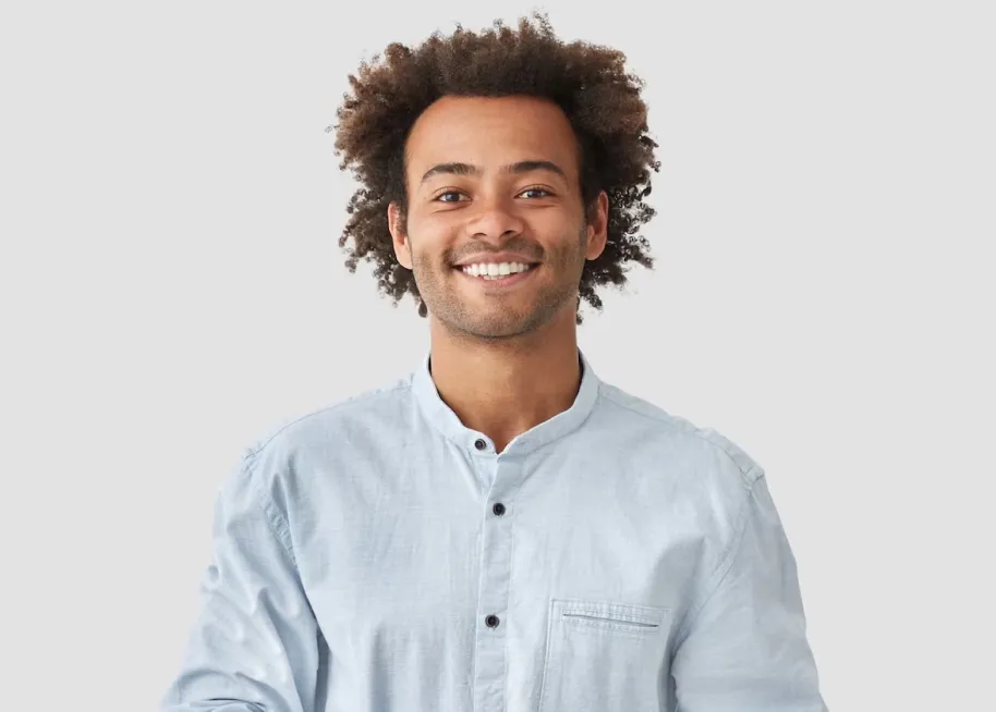
Emeline Siron
67k abonnés
Barthélémy Fendt
134k abonnés
Maud Alaves
102k abonnés
Mathieu Bernard
35k abonnés
Jim Halpert
Camera magician
Kevin Malone
Editor